The polarization analyzers SK010PA (sometimes referred to as Polarimeters) are universal polarization measurement devices and test systems for coupling laser beam sources into polarization-maintaining fiber cables. They were developed from practical experience with a focus on high usability.
The polarization analyzer is a plug&play device and connects directly to the USB port of a Windows device. The device is compact and can be easily integrated within existing systems. Alignments and measurements are performed rapidly. A real-time measurement of the Stokes parameters is performed and shown in an interactive display that depicts the state of polarization on a Poincaré sphere.
Measurement method
The radiation coupled to the polarization analyzer is passed through a rotating quarter-wave plate and fixed polarizer before being recorded by a photodetector.
The software SKPolarizationAnalyzer evaluates the Stokes parameters retrieved from a detailed analysis of the photodiode signal and the time/position information of the quarter-wave plate.
The state of polarization is then depicted on the Poincaré sphere, where any change in the state of polarization including the direction of rotation (depicted on the northern or southern hemisphere) is easily visible.
Polarization Alignment for Coupling into PM fibers
The SK010PA Polarization Analyzer provides procedures for the optimization of the alignment of the incoming polarization direction of the source with the polarization axes of the fibers and for the measurement of the resulting Polarization Extinction Ratio (PER).
The procedure starts with the recording of exit polarization states while the temperature is changed, or the fiber is carefully bended, to cause the exit polarization to fluctuate. A circle is then automatically fitted to the data points on the Poincaré sphere, and the mean and minimal PER are displayed.
The radius of this circle indicates the quality of the alignment, since it shows the angle deviation between the fiber polarization axis and the polarization axis of the incoming radiation. For an optimally aligned ideal fiber, the data circle converges to a single point, the center of the circle.
In the example shown, the circle on the Poincaré sphere has a large radius. During continuous measurement of the exit polarization state, the fiber axis is then rotated with respect to the polarization axis of the laser source. The optimum alignment is reached when the exit polarization state approaches the circle center on the Poincaré sphere as far as possible.
A second measurement then reveals the parameters of the optimized polarization alignment of the fiber.
Free Beam Measurements
The polarization analyzer can also be used for setting a well-defined state of polarization for free-beam applications. For these type of measurements, a correct alignment of the laser beam axis with the polarization analyzer is essential. This can be done using the microbench, or 40 mm cage system and using the connection with 4 rods or the rail system.
Adjustment of Quarter-Wave Plates
The SK0101PA Polarization Analyzer can be used to align and quantify retardation optics, e.g. fiber collimators 60FC-Q with integrated quarter-wave plates. For these collimators, the outcome polarization is adjusted by rotating the quarter-wave plate. Circularly polarized light is set when the poles are reached, with right-handed circular polarization located at the north pole, and left-handed polarization located at the south pole.
Standard delivery
- SK010PA of choice
- USB cable
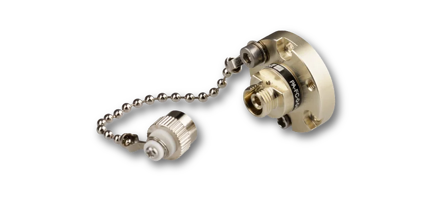
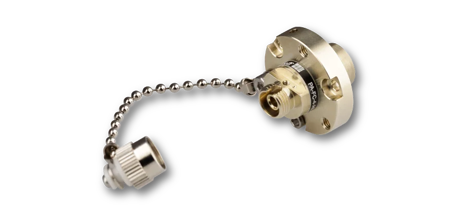
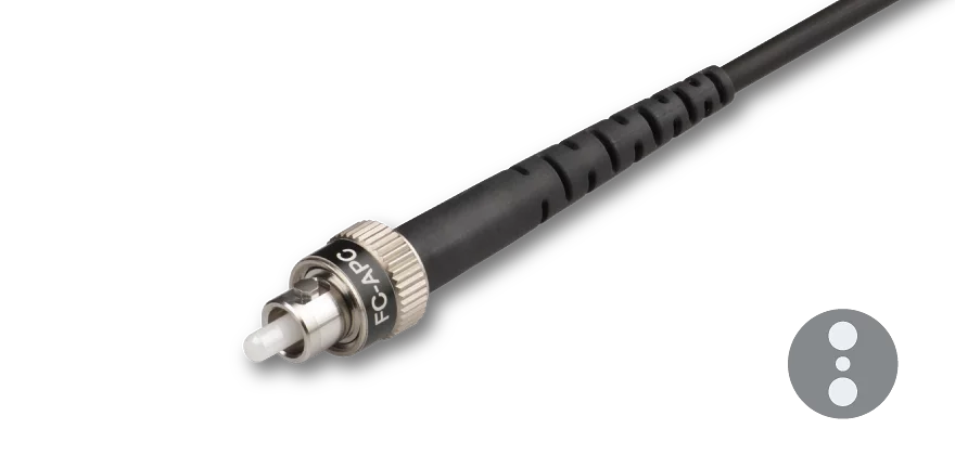
- Adapter for wide key fiber connectors of type FC APC PA-FC-4-0
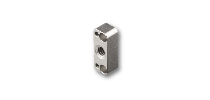
- Adapter for post-mounting PA-AP-M4
- Operating software: SKPolarizationAnalyzer for WINDOWS7, WINDOWS 10, WINDOWS Vista/XP (32/64 Bit)
- DLLs